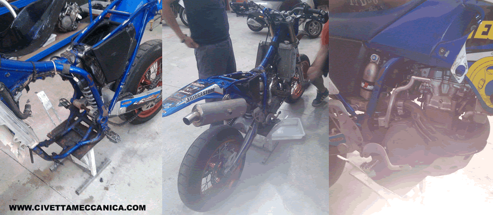
YAMAHA MOTORCYCLES / Problem resolution: Crankshaft seizure.
MODEL: YZ426F
PROBLEM: Crankshaft Seizure
In this blog I’ll comment with a little more detail the steps to disarm a motorbike engine, in this case a mono cylindrical YAMAHA YZ426F, as an instructional aid, it will help you to have a clearer idea to how to attack a serious problem as it is the engine seizure. To make more pleasant and short blog reading, i skip many steps, as i wrote before, i pretend with this article that you can be able to have an a good idea to how confront this kind of problems. The main idea of this, is reduce the 600 pages of the Yamaha Manual to only 20 at least! If you have any kind of questions about it, please write me. I´ll help you with your Yamaha Motorcycles.
In this post you will read about:
1. Analysis of Thermodynamic group.
2. Analysis of Clutch and Transmission System.
3. Analysis of the Charging System.
4. Open the Crankcase to get to the crankshaft
5. Final goals to get the bike back on track / Set up the distribution system
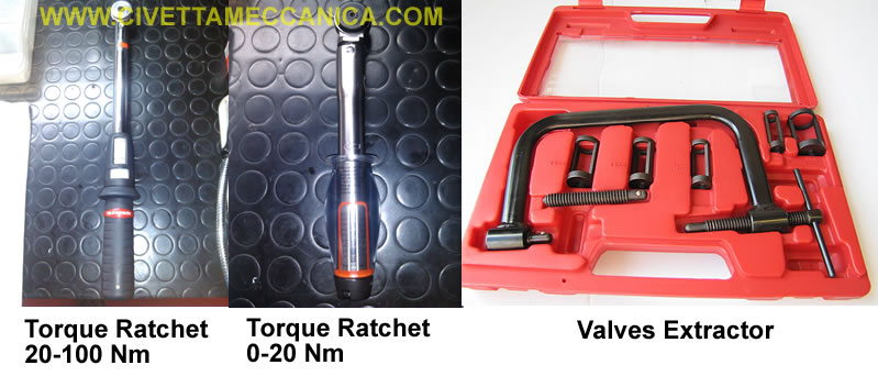
It is important to have in mind that for this kind of work you must have at least a few of “special” tools which i listed below (I assume that if you dared to face your Yamaha engine, you have something more than a simple screwdriver, brave man! If is so, continue reading!), as well as space for working comfortably, namely:
- Torque ratchet: (20-100 Nm)
- Torque ratchet (0-20 Nm)
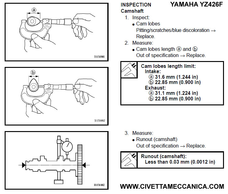
- Micrometer
- Small Oilcan
- Extractor for valves
- Gauges
- Vernier
- Manual YZ 426 F
1. THERMODYNAMIC ANALYSIS GROUP
1.1 FEATURES:
- Mono cylinder 4 stroke engine
- Double overhead camshaft (DOHC)
- Three (3) Valves admission
- Two (2) exhaust valves
1.2 EVALUATION OF THE ENGINE STATE
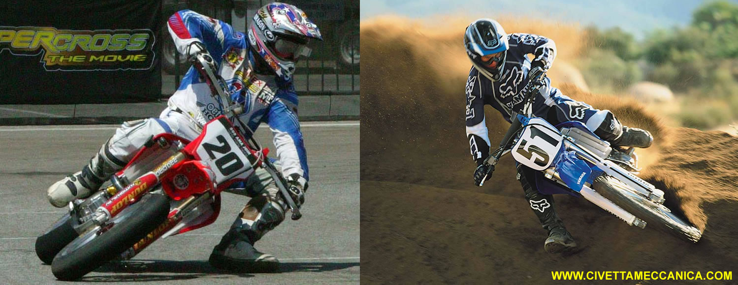
BACKGROUND: It is always important to know a little about the history of the motorbike, in this case, the main use for the YZ 426F was adapted to Supermoto, the engine is the original, only suffered modifications of the chassis. We have brought this motorbike for the rider while training in a circuit, the engine would not restart, he commented “the engine won’t start, its blocked somehow” is also good to know not only how its using the motorbike, it is more important to know what the rider says.
1.2.3 PROCEDURE
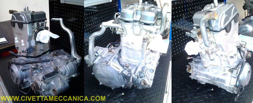
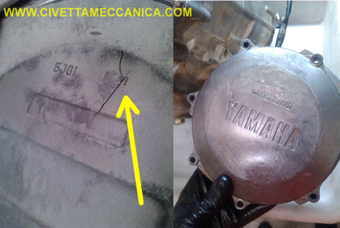
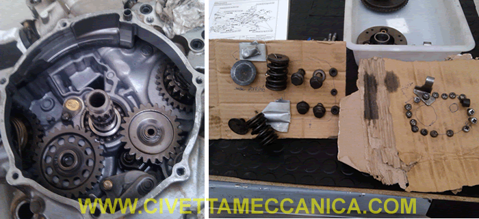
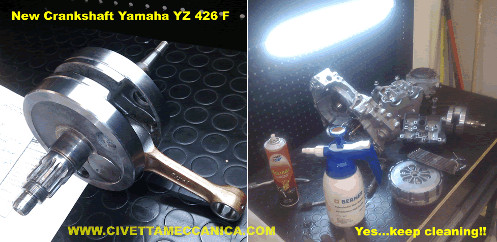
- The first thing to do is clean up the engine, leave it clean, as seen in the pictures above.
Having done this, I noticed that the clutch cover had a fissure, through which leaked oil, almost imperceptible, but with the continued use during the training week, became a significant problem.
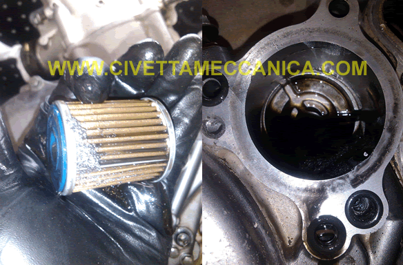
- An important step before doing anything, drain all the engine oil and fluids, in this case I was not surprised to realize that the engine only had about 300 ml of engine oil; i assume a crankshaft or piston seizure / suppose this is not a crazy idea.
when I removed the oil filter, I was expecting what was coming… I saw a lot of metal shavings, undoubted sign of an engine seizing.
We tried to move the crankshaft manually, to see if the system is blocked.
- Indeed, the system was blocked, i tried to turn the crankshaft but reaches the point of not following cyclical movement.
- Proceed to remove the valve cover.
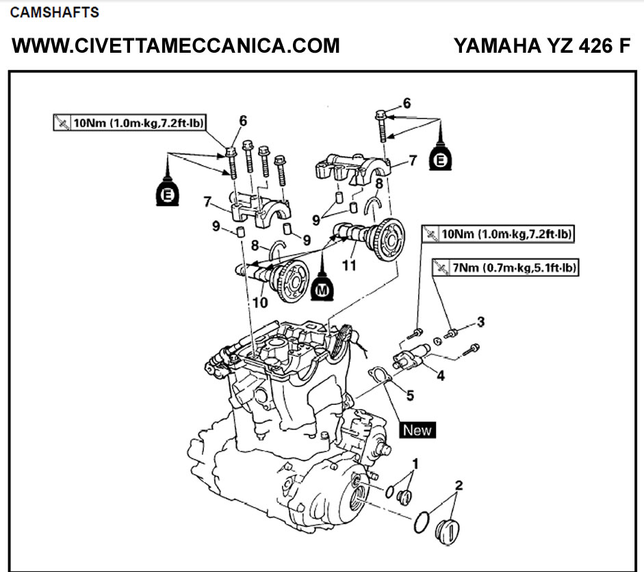
- Extract the distribution chain tensioner, this in order to free the gears of the camshafts.
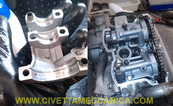
- We extract the parts that hold the camshaft to the cylinder head.
- Please, always keep your manual handy! This is what differentiates a professional from an amateur. Soon I’ll upload the complete manuals of the bikes I publish.
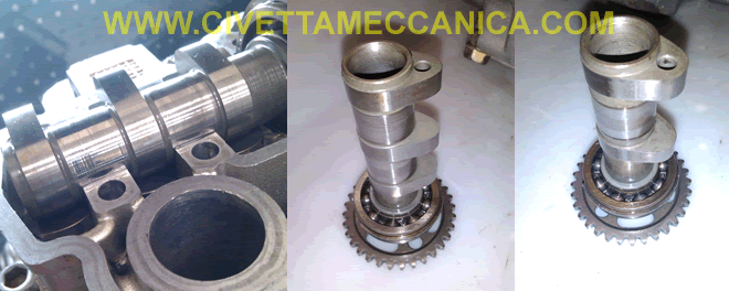
And with that, we can completely remove both camshafts (Admission have 3 cams; Escape have 2 cams).
ADJUSTMENT VALVE: (Use the gauge)
- Exhaust valves clearance: 0.26 mm (both)
- Intake valves clearance: 0.20 mm (all three)
We continue with the process of disarming the engine, the next step; cylinder head.
- We try always to have the distribution chain at hand (it does not fall into the engine), even when we know we are going to dismantle every last piece of the engine. We do this to keep order and professionalism in everything we do.
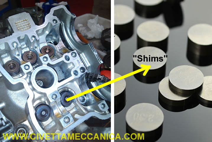
- Proceed doing the measure of the “Shims” of the valves (take a look of the image below). When you will going the reassemble camshaft, you can be able to make a successful valves adjustment. (Soon I’ll be posting a blog of the basic theory to bear in mind how to make this procedure on a Ducati, if you know what to do with a Ducati, you do it with any motorbike!)
Exhaust valves (Expressed from left to right: Left / distribution chain): For this procedure we will have to use a Vernier.
- “Shim valve left”: 1.74 mm
- “Shim right valve”: 1.78 mm
Intake valves (Expressed from left to right: Left / distribution chain): For this procedure we will have to use a Vernier.
- “Shim valve left”: 1.70 mm
- “Shim central valve”: 1.78 mm
- “Shim right valve”: 1.70 mm
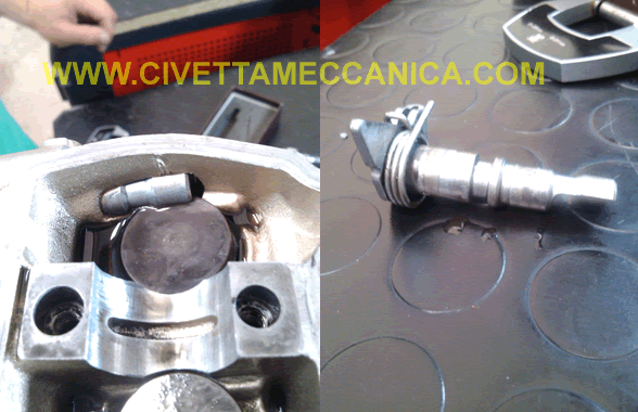
In this particular case, this motorbike has a “decompression mechanism” on one of the admission valves, that’s to decompress the engine when we start, in the order to make an easy engine start; It is very common in this type of motorbikes and old high-powered motorcycles; all it does is open a valve to let air escape.
• The decompression mechanism operates mechanically on this bike, you have to activate manually with a lever on the handlebar, near the clutch lever.
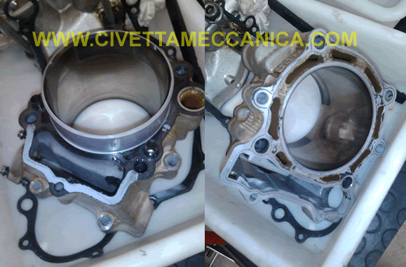
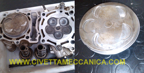
• proceed to remove the cylinder head block, being careful not to damage the cylinder, this seizure not necessarily mean that the cylinder is damaged. Generally it is, but this was not the case.
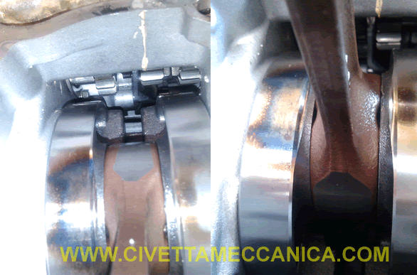
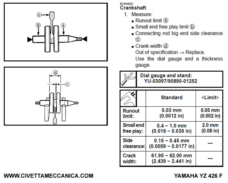
• As discussed above, the problem comes from a seizure Crankshaft / rod.
• Try to move the system now without camshaft simply grabbing the piston and try to move the piston, in this case is fully stuck, it shows in the picture, where it was welded by extreme heat and lack of oil in the area.
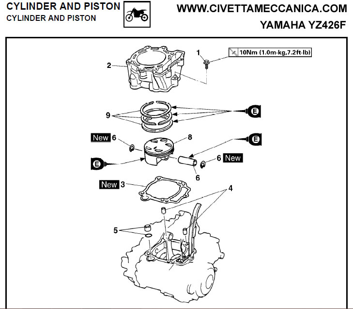
CYLINDER YAMAHA YZ 426 F
- Again, we try to clean all the best we can, especially the galleries of the cylinder block which the coolant pass through. Since we get here, we will make things right! So i hope you have very careful with this. If you have some kind of problems…keep calm and write me!
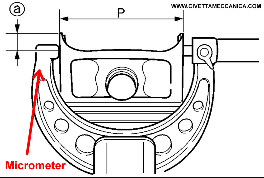
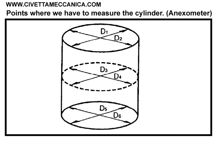
- The most accurate way to measure a piston, is with a micrometer, making three measurements at different heights of the piston, as would the cylinder. Why? The piston isn’t cylindrical as many think, in fact is conical. As shown in the image below….
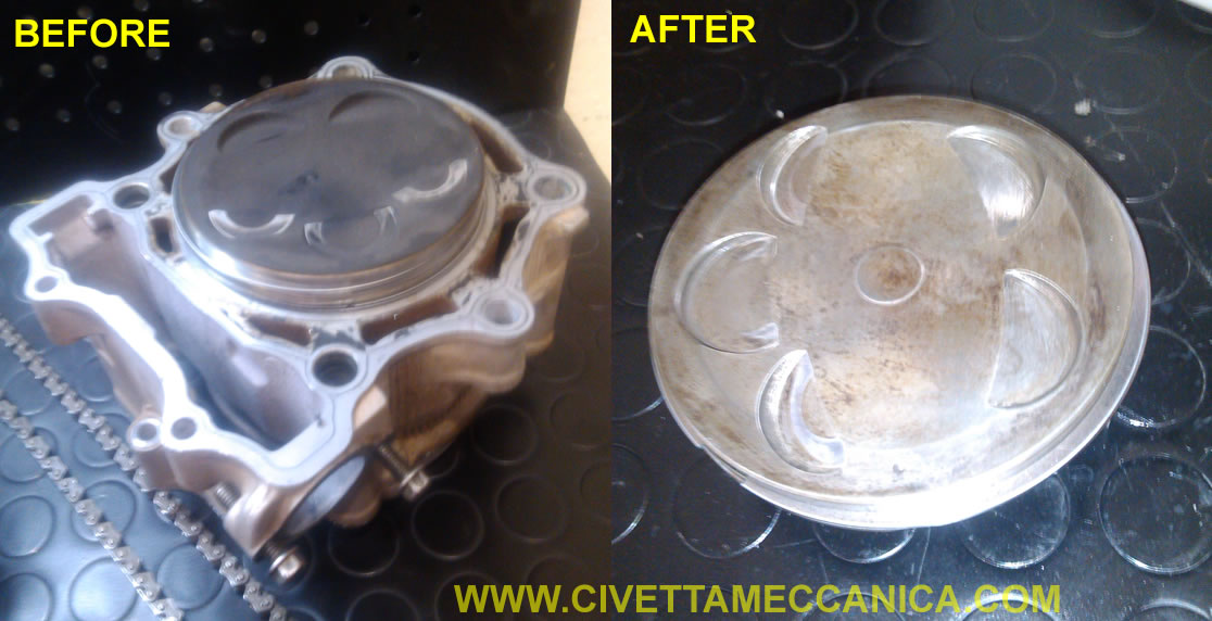
• Once removed: cylinder, cylinder head and piston. Proceed to clean everything, take all possible char. In this case, the piston not damaged, either the cylinder. So we must continue with the removal procedure up to remove the crankshaft with his rod.
• At this time, we can without any problem, starting with the removal of the valves.
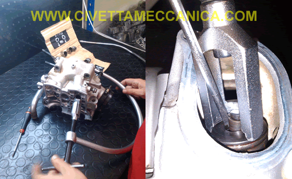
• To do this we will need an extract valve (generic), we verified that we have the best attack of the coupling spring, to make more safely, and pushing this, we get the “cotter” being careful not to move the extractor, this operation is the most dangerous in mechanics, a spring released an impressive amount of energy, if we do not properly secured, it is a real bullet, it is recommended to wear safety glasses.
- NOTE: where i put a close-up image of the extraction of the “valve cotter”, that belongs to a KTM 690 Supermoto, i placed in here because when i was making this process with the Yamaha YZ426F i didn’t have the camera. I apologize for that!. The principle is exactly the same, in fact, do this in the KTM is much more dangerous.
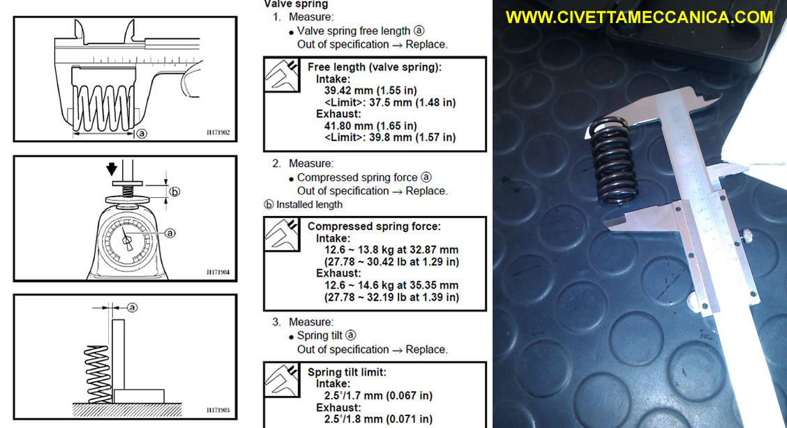
- Once we have the springs out of the cylinder head, we proceed to measure them to make sure they are in good condition. (Always keep the workshop manual of your motorbike), in this case the service limit measures are:
Admission: (According Manual: 39.42 mm), in our case (Expressed from left to right: Left / distribution chain): For this procedure we will have to use a Vernier.
“Left spring valve”: 39.4 mm
“Central spring valve”: 39.4 mm
“Right Valve Spring”: 39.4 mm
Escape: (According Manual: 41.80 mm), in our case (Expressed from left to right: Left / distribution chain): For this procedure we will have to use a Vernier.
“Dock valve left”: 41.8 mm
“Right Valve Spring”: 41.8 mm
- To follow this procedure, we have to start to dismantle the charging system of the bike, such as transmission and clutch, then separate them crankcase and crankshaft with his rod. We need to continue reading!
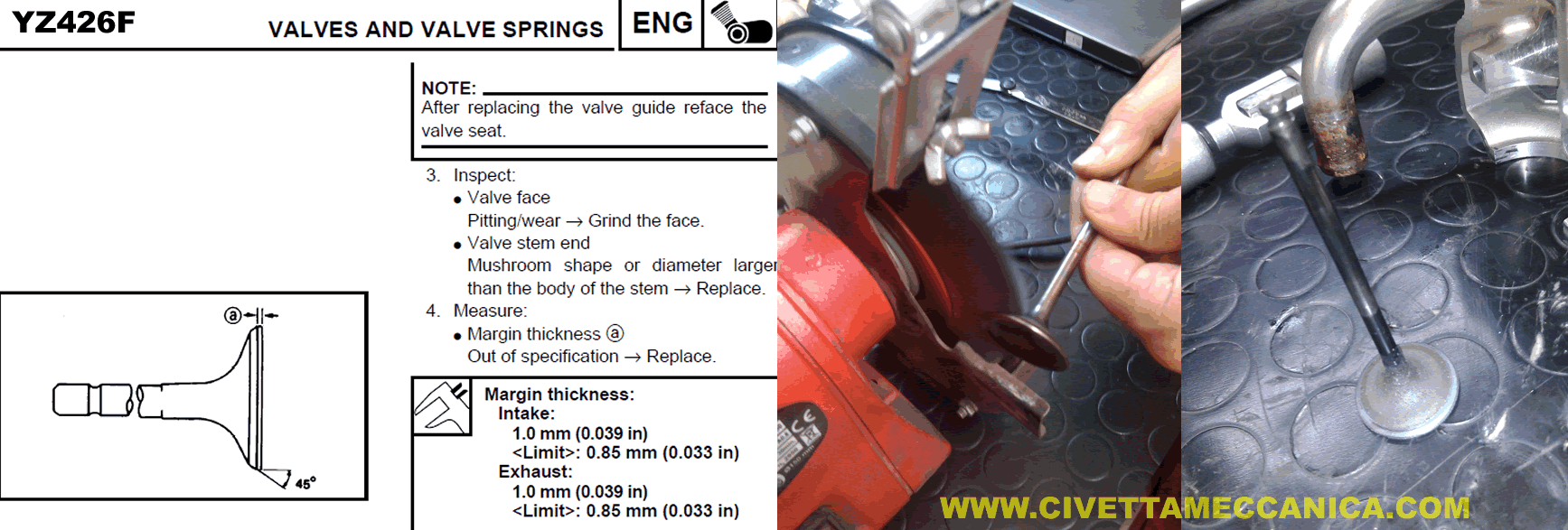
- Proceed to remove the coal stuck in the valve seat. Always use a very fine sandpaper wheel, this procedure is somewhat delicate, if you modify the valve seat, you will have serious problems in the set-up, having to buy new valves. All we seek here is to remove the dirt, not modify the metal surface.
2. ANALYSIS OF: CLUTCH AND TRANSMISSION SYSTEM
2.1 System Features
• Manual Gearbox 5 speed.
• Lubricated by the same engine oil.
• Secondary transmission chain.
2.1.3 PROCEDURE
To get to the transmission system, we have to remove the clutch system of the bike. It is very strange that the gearbox serious harm for seizure of crankshaft (in this type of bikes) we want to access the gearbox for gear inspection, cleaning, shift selector, remove traces of metal chips from the seizure of the crankshaft. To do this I will make a mild explanation of how to make the extraction of the clutch assembly without the locking clutch necessary for this procedure.
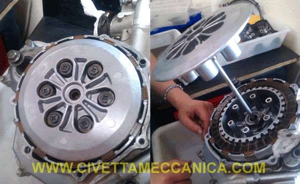
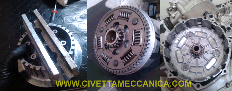
- To remove the top clutch pressure will have no problem, loosen the six (6) bolts can be done with the right tool without any exhaust.Where we are going to have trouble, is not having the corresponding extractor (our case), to loosen the main bolt the clutch, we will see to easily remove the pressure cap and clutch springs.
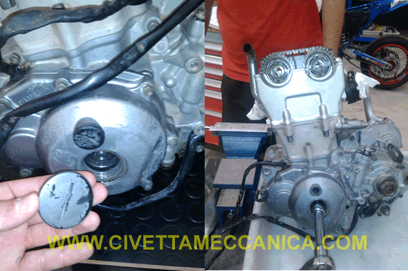
- To do this we will use two pieces of aluminum as makeshift restraints. For such procedures always use aluminum as the main material for its ductility, we avoid damaging the clutch housing with straining. (In the picture below, this it is shown, and with the clutch out)
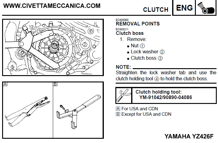
- If you have money to buy the original clutch extractor, I recommend to buy it, attached image Tool Workshop manual.
CLUTCH PARTS ORDER YAMAHA YZ 426 F (See image Yamaha manual)
1. Clutch Cover
2. Gasket
3. Dowel Pin
4. Clutch Spring
5. Pressure Plate
6. Push rod 1
7. Circlip
8. Plain Washer
9. Bearing
10. Push rod 2
11. Clutch Plate
12. Friction Plate
13. Nut
14. Look Washer
15. Clutch Boss
16. Thrust washer
17. Clutch housing
18. Push Lever
MEASURES FOR THE CLUTCH:
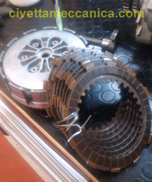
Whenever we disarm an engine, we must take steps before and after this procedure; as we are with the clutch, we will measure the friction plates, arranged in order from external to internal of the clutch:
• Plate 1: 3 mm
• Plate 2: 3 mm
• Plate 3: 3 mm
• Plate 4: 3 mm
• Plate 5: 3 mm
• Plate 6: 3 mm
• Plate 7: 3 mm
• Plate 8: 3 mm
The service limit according handbook is 2.7 mm. So we are within the limit, do not replace the clutch discs. The clutch plates by the other side (made of metal) was all changed in this motorcycle, therefore had considerable warpage (0.2 mm) and also about over heated, so we were replaced with new ones; these discs are not measured by its thickness, warpage of the disk is measured relative to a perfect plane; Using a gauge and a base perfectly straight, in this case, a “marble” calling that way in the Spanish slang of workshop (at least in Spain, it is)
- Having already clear path, we can continue dismantling. The following is the side of crankcase cover (clutch side). I recommend that in this procedure you make a cardboard model of the cover, to sort the bolts once removed, are often of different sizes and when we are assembling the engine, we lose a lot of time looking for the right screw.
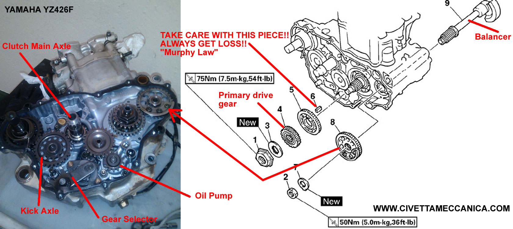
- Since we are dealing with an seizure engine, full of metallic particles inside it, we will need to clean all the oil pump system.
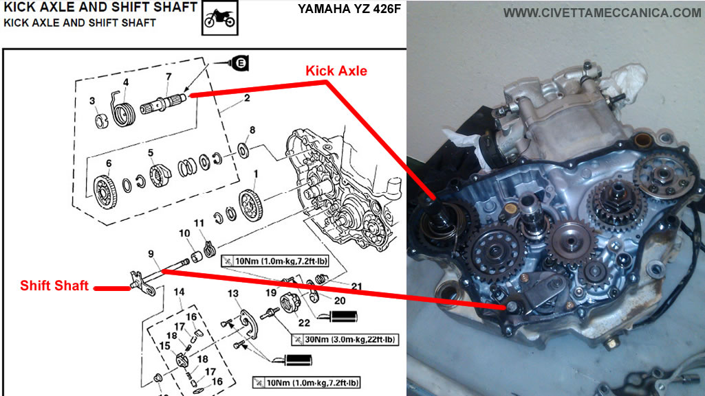
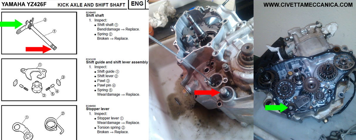
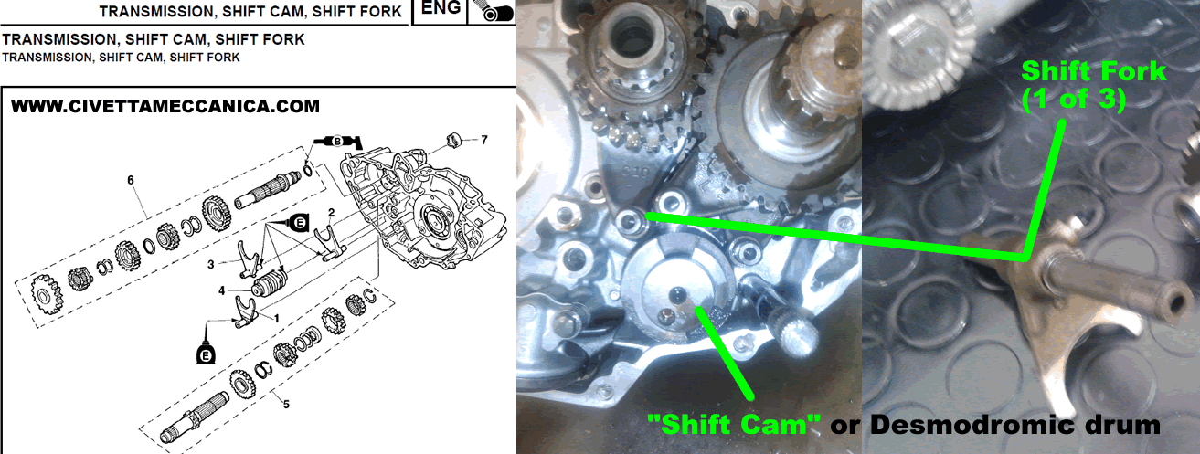
- Once this is done, we will remove the “Shift Shaft” (see picture), this method is easy, it is simply an axis that through the engine longitudinally, this is the mechanism for transmitting the force of your foot on the shifter to the desmodromic drum inside the engine, this piece doesn’t suffered any damage because of the engine seizure.
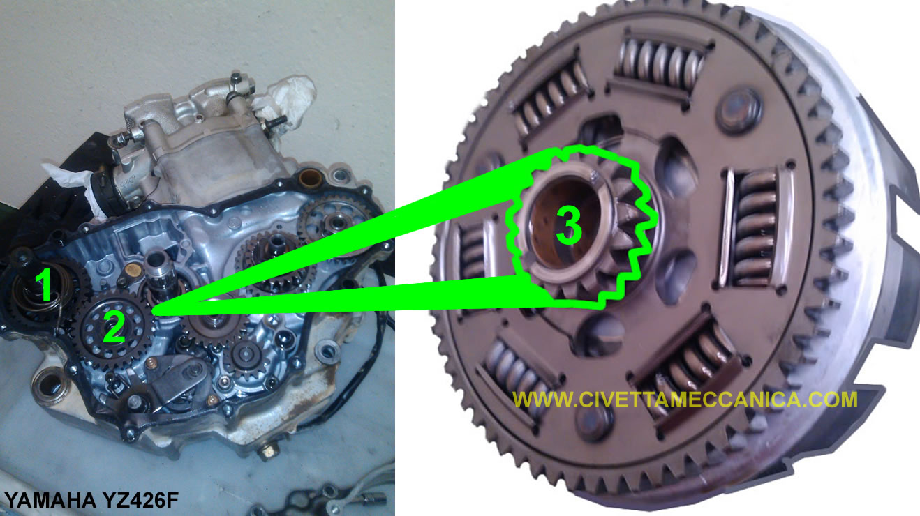
- Then we will remove the “Kick Axle”. The way this system works is: When you give the starter kick, a sprocket “Kick Axle” moves another sprocket which in turn connects to the “clutch housing”. As this is the latter piece is connected to the crankshaft, you are directly moving the crankshaft with your leg (that’s why the “decompression system” in the cylinder head works for. Then, the spring that you see in this piece, works for return the kick lever. In conclusion, we have a chain of three (3) sprockets. (See picture: Sprocket 1, 2 and 3)
3. YAMAHA MOTORCYCLES CHARGING SYSTEM (CDI MAGNETO REMOVAL)
3.1 INSPECTION CHARGING SYSTEM:
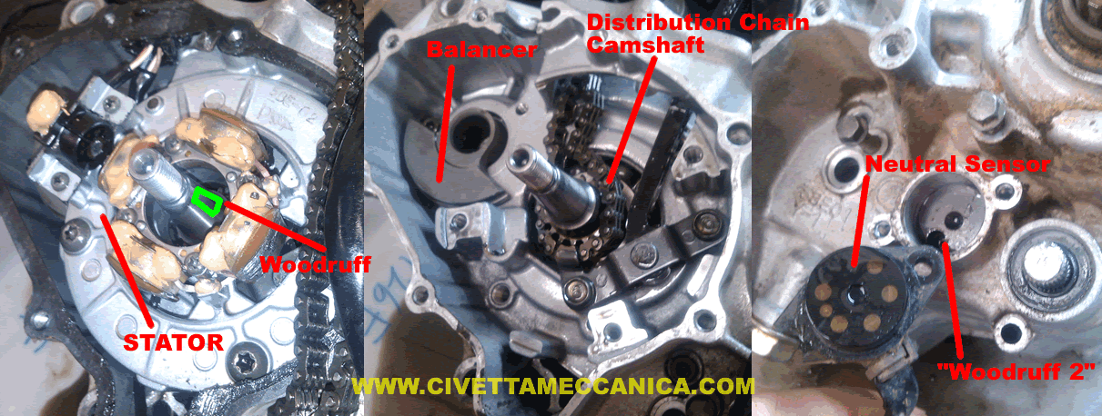
- When you remove the lid of the stator, realize that the flywheel is full of metal shavings inside (see the images below). Do not worry, this does not mean that the system is damaged, but to dismiss this, we must first clean all debris generated in the engine area (Charging system).
- After cleaning everything, we proceed to remove the pieces. One tip i give you mate: check whether the inside of the flywheel if there are scratching or rubbing metal marks. If so, there are chances that you have not only a crankshaft seizure, but also a significant imbalance of the counterweights; this can damage: The flywheel, the pick up sensor and bearings. This occurs (when it happens, this is not our case) because when the flywheel is spinning (integral with the crankshaft), collides with the stator. This gap that must exist between the two elements we will call “air gap” in British slang probably have another name (in Spain they call it that way).
- Be careful with the piece “Key woodruff” If you lose this piece will not be able to re-arm the system. Losing these kind of pieces is something that happens very often in workshops, you may not be aware that you are charged to your bill a new one, but the workshop will tell you that it’s was a damage piece (but that’s between you and me!), So if you take your motorbike to a workshop, be one that always some friend of yours recommended, there is no more effective tool than honesty nowadays. Its function is exactly the same as the small piece that we saw on the clutch side, remember? (see the last picture) It’s just a safety component to help fit another pieces.
- In future blogs, I will post how to test these elements. (Multimeter)
- When we get out the crankcase cover (left), we proceed with the extraction of the flywheel, then, you have to be careful with another little piece on the main axle, yes, another “woodruff key“. Put it in to a safe place (plastic box or something like that)
- You can at this point, extract the neutral sensor, it’s located just beside the flywheel, on the crankcase cover. This part it’s a tricky one, because you have to extract another little piece, is a small cylindrical part ubicated into the crankcase cover, this piece attached the desmodromic drum of the gear box.
4. OPEN THE CRANKCASE TO GET TO THE CRANKSHAFT
- We finally got to the most interesting part of our case (seizure of the crankshaft).
What we do now is remove all screws around the crankcase, as I said, make a cardboard or paperboard to sort screws you extract. - When you do this, do not be surprised, the crankcase can not be separated even not having screws. For this you must use a mixture of brute force and finesse. Note: Never use a metal hammer, only those made of nylon or some soft material is used.
- How we do this? Do not banging like a madman!. Much of this is given by the experience, but I can explain to you without any problem. Always points to the robuster side of the crankcase, this engine for example, has an “special fins”, not for banging, but for to use a screwdriver as a lever (Japanese people. … always thinking in everything), please observe the picture.
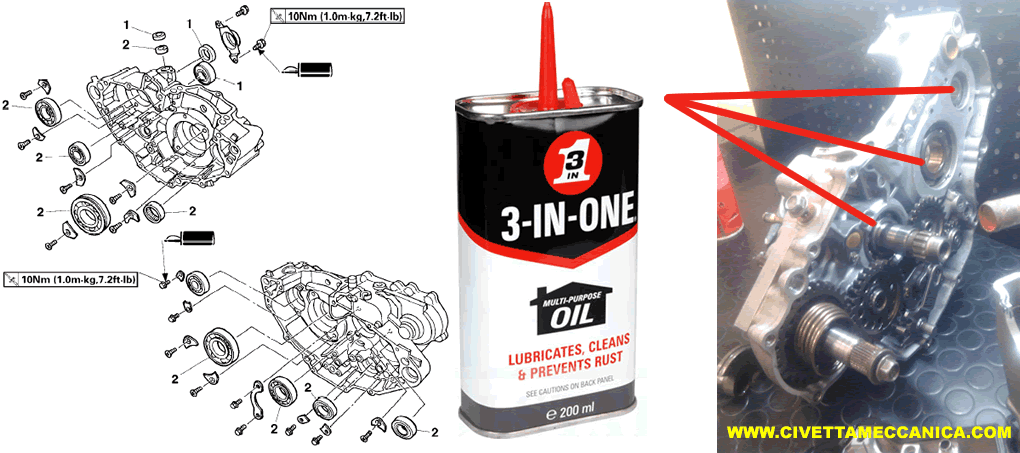
- In our case, you don’t need to change the bearings, what we gonna do however is cleaned thoroughly without disassembly. That’s because there is metal dirt inside the bearings. For this we will use any product that promotes metal lubrication, for example, 3 in 1.
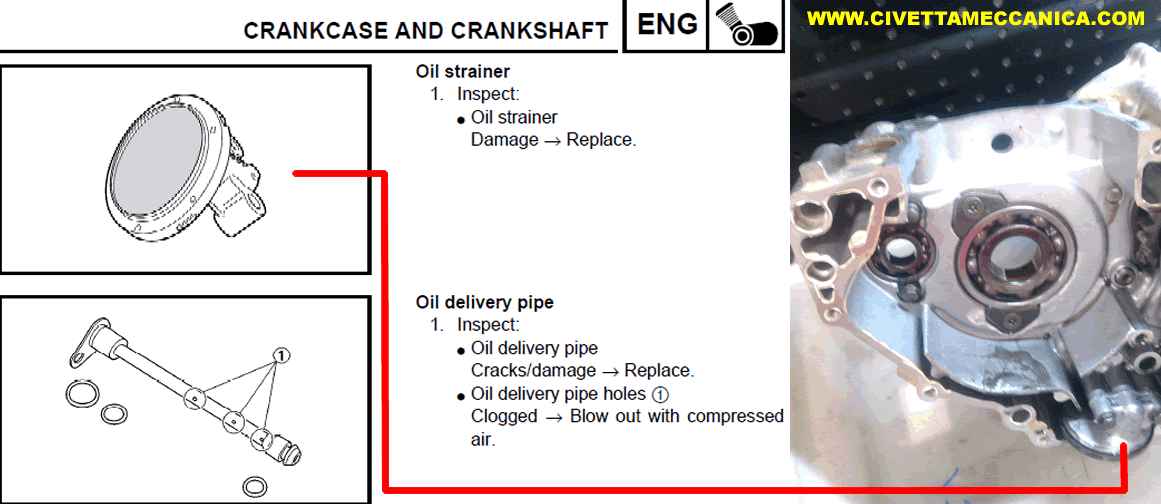
- Another important step in these cases of seizure, is removed and cleaned completely the “Oil Strainer”, that will have metal debris that block the lubrication when we closed motor. It is an easy process, has no complication.
- Remove the crankshaft seizure, in these cases there are two options, which will depend entirely on the savings you have in the bank:
1) Buy whole new system (crankshaft, connecting rod)
2) Send to a grinding company, Seized crankshaft and connecting rod. If they are good, they stay as well as a new one, and most importantly, you save about 200 pounds! isn’t that much really when you compared with the Yamaha R1 crankshaft, that rounds about 1.500 – 2.000 pounds, in perfect conditions. So! Love your YZ 426 F mate! (This is the new crankshaft for our Yamaha YZ426F)
- We extract the gearbox, gears this to clean the metal remains. This is a very delicate process, if you aren’t sure, apply a little gasoline or 3 in 1 between gears to drain the dirt. Draw or take photos of the system before decommissioning. (In this blog does not explain the process, expected future updates)
5. Final goals to get the bike back on track.
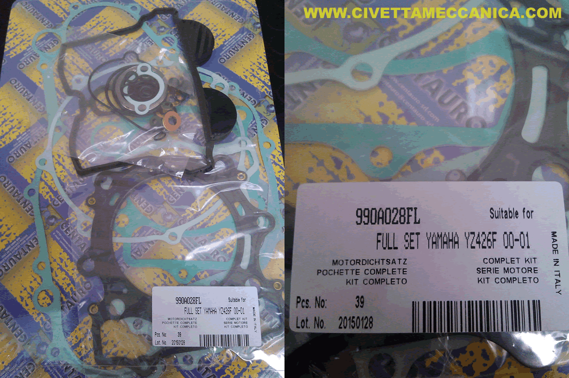
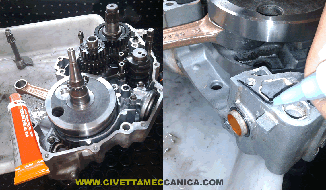
- After cleaning everything, crankcases, bearings, gearbox and lubrication system (oil pump); the first thing you have to do is change all the gaskets. Always replace with new ones! The kit of gaskets for this kind of motorcycles aren’t expensive.
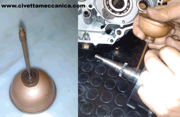
NOTE: Always, before installing any mechanical part that has some kind of friction or movement, keep it well-oiled before closing the engine. Namely:
1) Cams
2) Bearings
3) Cylinder
4) Piston
5) Piston Pin Clip
6) Crankshaft
- First, we have to verified that the crankshaft is well placed also the transmission system (always placed on neutral changes before closing the engine !!)
- Make sure enter all changes before closing the crankcases. This is a very common error.
- Then when we know that we have everything in order to close the engine, proceed to place gaskets. In this case, it has no gasket, instead we will place a sealing compound, before doing this, we have to make sure there is no dirt where you place the sealing compound.
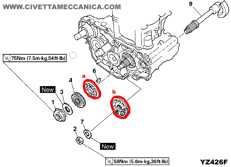
- Another process that takes care, is the installation of “Balancer”. Just go in one way, you have to match the points (see the image below); These are the sprocket of the crankshaft (a) and the sprocket of the “Balancer” (b)
5.1 SET UP THE DISTRIBUTION SYSTEM
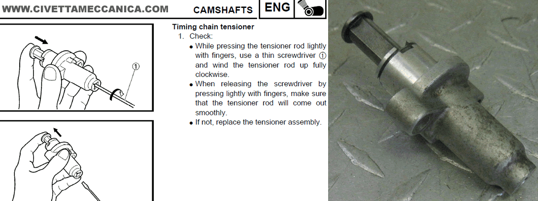
- Now, that we have to do is check the operating status of the distribution chain Tensioner.
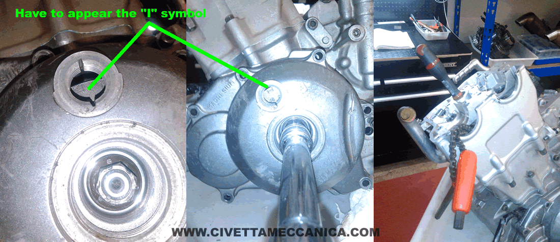
- Then, you have to place the piston at top dead center. There are two ways to do this:
1) Put a screwdriver carefully in the spark plug hole, then turn the crankshaft (counterclockwise) to see how the screwdriver goes up entirely with the movement, then when just shows signs of starting down, stop!
2) With flywheel cover in place, see the hole while turning the crankshaft, until you see the symbol ” I “. You doesn’t use the “H” symbol for this process, is used only for use with the “Timing Light gun”.
- Having the system in TDC, we will place the camshafts. (Intake and exhaust).
- For this step, we have to align both points in the sprockets of the camshafts, and also align the letters “E” and “I” (see picture below).
- NOTE: Do this without the “Chain tensioner” installed.
- Then when we have the distribution chain and the camshaft in place, we proceed installing the chain tensioner.
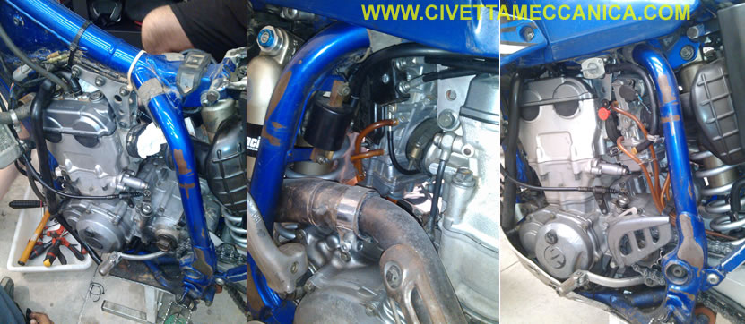
Now that you have completed this, it only remains to install the engine in the chassis! I just hope this blog have been helpful for you as orientation guide. Remember, you can always email me!
Thanks for reading my article, now GAAAASSSS !!
